
Digital Logic Is Not Just for Computer Science Part 1

Please don’t forget to subscribe:
and please don’t forget to give a donation:
Introduction to Digital Logic
Logic is used to make decisions. Generally speaking, the decisions we make are determined by rules that we know about the world. The decisions we make are based on whether or not these rules are true or false in a given situation. For example, if we see a nail sticking up from a piece of wood on the ground, we will decide to avoid it. This is because we know, as a rule, that nails are sharp AND that sharp objects pierce our skin. The diagram below will demonstrate what I am on about:
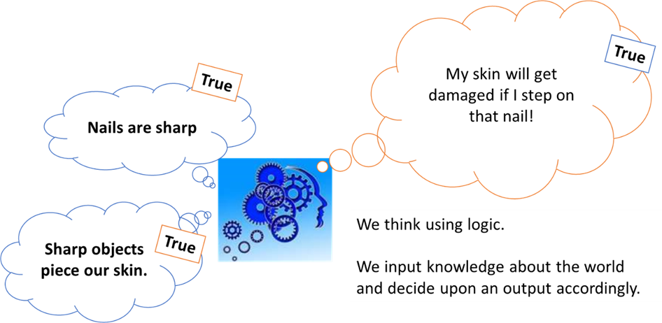
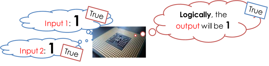
Human logic works with rules / facts / statements which are either True or False. Computers have been designed to do the same. Binary logic is what a CPU uses to make decisions based on the inputs it receives. The CPU (like us) will take inputs which may be true or false (1 or 0) and make a decision which will produce a particular output.
There are very few logic operations that a CPU will perform on its inputs. However, combinations of these lead to incredibly complex calculations. The logic operations that a CPU will perform are:
· The NOT operation
· The AND operation
· The OR operation
· The XOR Operation
Electronics engineers have developed components that can carry out the AND, OR, NOT and XOR logic operations. The CPU is full of millions of these components.
The Different Logic Gates and Truth Tables
A circuit board can be found inside most digital devices. It is a flat, thin board that has tiny electrical components built onto it. Many electronic circuits have to make decisions. They look at one or more inputs and use these to determine the outputs from the circuit. The process of doing this uses electronic logic, which is based on digital switches called gates. Many electronic circuits have to make decisions. They look at one or more inputs and use these to determine the outputs from the circuit. The process of doing this uses electronic logic, which is based on digital switches called gates. Each input and output of the logic gates must be one of two states:
· True or 1 or on
· False or 0 or off

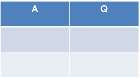
A truth table is a specific table that will have all of the rules for combining logical expressions written down. Truth tables are used to work out the different combinations of inputs that a given logic gate could receive and the resulting outputs that are created from its operation. Below is a typical example of how a truth table would be laid out:
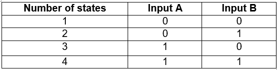
A single digital signal has only two states - on or off. However, if you use two inputs you can double the number of possible states, to four, to eight, to sixteen. In a logic gate, each combination of input signals can be made to produce a different outcome. Binary numbers reflect the two states - on and off, 0 and 1 like we established. Logic gate calculations can also be represented as truth tables.
Think of a logic gate as a light switch. Let us look at the individual logic gates:
NOT Gate

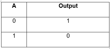
This is a NOT Gate. A NOT gate has just one input. NOT tells us that Input A has to be 0 (or OFF) in order for the output to be 1. Otherwise the output is 0. A NOT gate is sometimes called an inverter. The light switch is off but the light is on.

Below is a typical example of a truth table for a NOT gate:
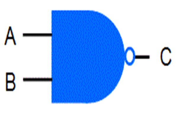
AND Gate

This is an AND Gate. An AND gate usually has two inputs. AND tells us that both Input A AND Input B have to be 1 (or ON) in order for the output to be 1. Otherwise the output is 0.
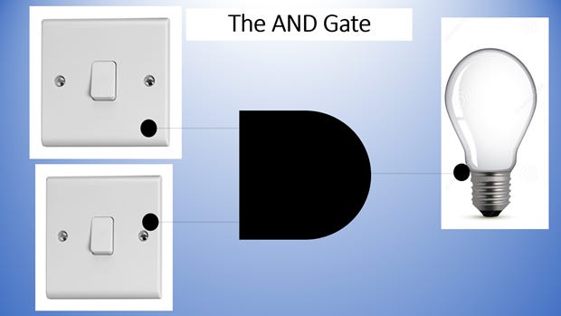
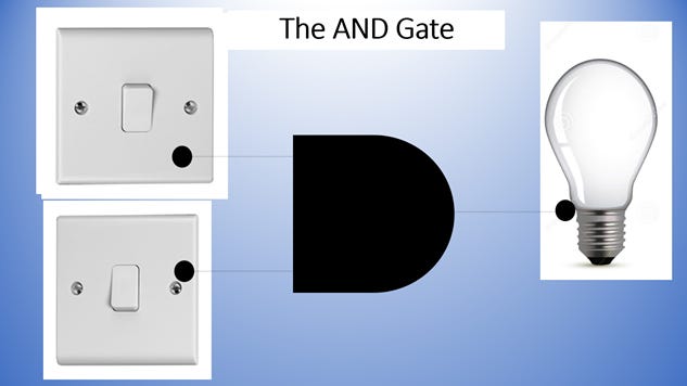
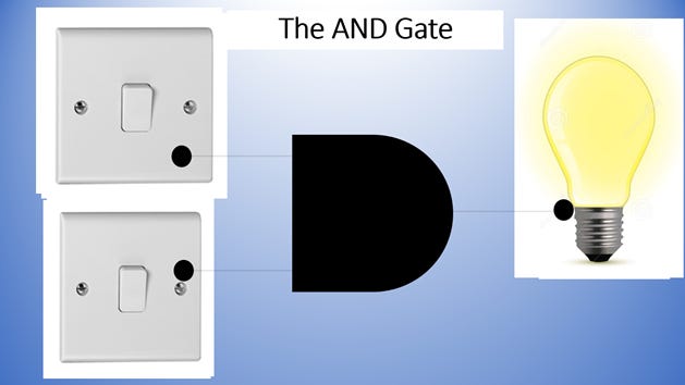
What you can see from an AND Gate is that both light switches have to be on for the light to be on otherwise, the light will remain off. Below is a typical truth table for an AND gate.
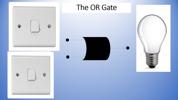
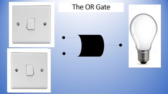
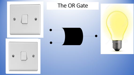
OR Gate

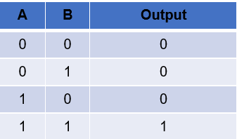
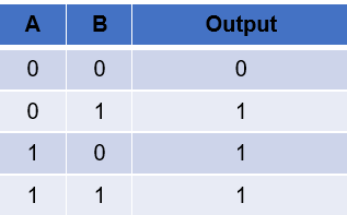
This is an OR Gate. An OR gate has two inputs. OR tells us that EITHER Input A OR Input B has to be 1 (or ON) in order for the output to be 1. Otherwise the output is 0.
From what you see if that with OR Gates, both switches have to be off for the light to be on. Anything else will mean the light remains off. Below is a typical truth table for an OR gate.
XOR Gate
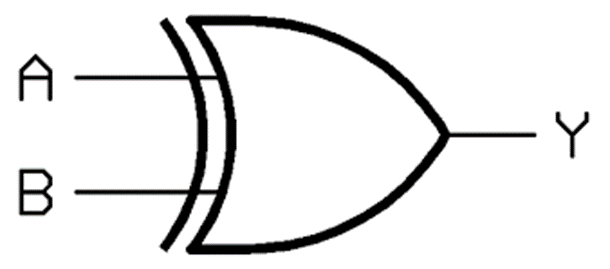
This is an XOR Gate. An XOR Gate has two inputs. XOR tells us that if either Input A or Input B has to have a 1 and a 0 to be a 1 (or ON). If both inputs have a 0 or a 1, then the output is 0 (or OFF). In the context of a light switch, one light switch has to be on and another has to be off for the light to be on otherwise, the light will remain off. Below is a typical truth table for an OR gate.
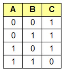
NAND Gate
A NAND Gate is a combination of both a NOT and an AND Gate.
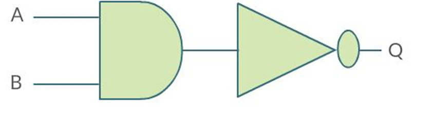
This is used so commonly in computing that this is considered a bespoke operation and given its own symbol. This is what a NAND Gate looks like:
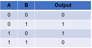
The NAND gate is the same as an AND gate followed by a NOT gate. It inverts the output from an AND gate. Below is a typical truth table for a NAND gate.
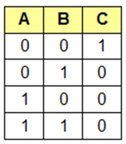
NOR Gate
A NOR Gate is a combination of both a NOT and an OR Gate.
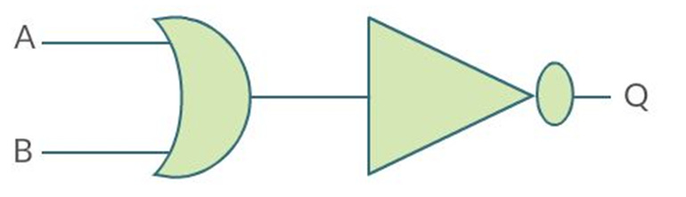
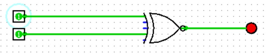
This is used so commonly in computing that this is considered a bespoke operation and given its own symbol. This is what a NOR Gate looks like:
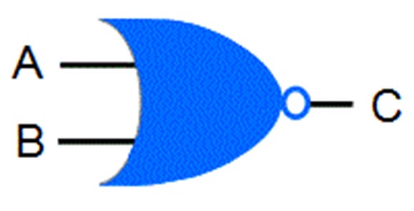
The NOR gate is the same as an inverted OR gate. It inverts the output from an OR gate. Below is a typical truth table for a NOR gate.
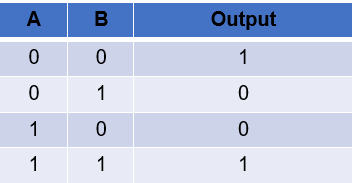
XNOR Gate
This is an XNOR Gate, which is also referred to as an Exclusive-NOR Gate. Like the XOR Gate, the XNOR Gate has only two inputs. An XNOR Gate has two inputs. XNOR tells us that if both Input A and Input B have to have a 1 and a 0 to be a 1 (or ON). If one of the two inputs have a 0 or a 1, then the output is 0 (or OFF). In the context of a light switch, two light switches have to be on otherwise, the light will remain off (Floyd, 2000). Here is a typical truth table for an XNOR gate.
Don’t miss Part 2 of the Logic Gates Is Not Just for Computer Science as I will be writing about how logic gates are made and then in part 3, I will be writing about logic gates in semiconductors.
Reference List
Bradley, R. (1999) Understanding Computer Science to Advanced Level Fourth Edition Cheltenham: Stanley Thornes (Publishers) Limited
British Computer Society. Glossary Working Party, (2005) The BCS Glossary of ICT and Computing Terms Eleventh Edition Harlow, Essex: Pearson Education Limited
Comer, D. E. (2005) Essentials of Computer Architecture New Jersey: Pearson Education Inc.
Englander, I. (2014) The Architecture of Computer Hardware, Systems Software and Networking An Information Technology Approach Fifth Edition, Hokoben, New Jersey: John Wiley and Sons Inc
Floyd, T. L. (2000) Digital Fundamentals Seventh Edition New Jersey: Prentice-Hall Inc.
Heathcote, P.M. Langfield, S. (2004) A Level Computing 5th Edition. Oxford: Payne-Gallway Publishers Ltd
Morton, D. L. Gabriel, J. (2004) Electronics The Life of a Technology Westport: Greenwood Press
Sze, S. M. Kwok, K. NG (2007) Physics of Semiconductor Devices Third Edition New Jersey: John Wiley & Sons, Inc.
Thomas, M. Surrall, A. Hamflett, A. (2017) A/AS Level Computer Science for WJEC/Eduqas Student Book Cambridge: Cambridge University Press
Please don’t forget to subscribe, share and donate.