
Physics of the Central Processing Unit

Introduction
Ever wondered what makes your computer, laptop or phone actually work? Look no further as you have come to the right place. This article is jam-packed with how the computer works, with a particular focus of how the Processor works. How you ask? It is a good idea to get into Physics and Electronics including my personal favourite - as they say, save the best for last.
Introduction to Physics
We define physics as the study of the physical world including matter, motion and behaviour through space and time and related entities of energy and force. Physics is a huge subject with a lot of areas we can go into. These areas are as follows but not limited to:
· Electronics
· Waves
· Astrophysics
· Nuclear Astrophysics
· Forces and Motion
· Electricity and Electromagnetism
· Quantum Physics and its Relationship with Quantum Computing
Physics and Computer Science are two complementary fields. Physics provides an analytic problem-solving outlook and basic understanding of nature. Computer Science enhances the ability to make practical and marketable applications, in addition to having its own theoretical interest. Physics and Computer Science overlap in the following ways:
· Electronics: Logic Gates, Truth Tables, Karnaugh Maps, Boolean expressions
· Computer Science: workings of the CPU
· Computer Science: Overclocking the CPU
· Computer Science: Storing sound in data representation
· Physics: Waves
· Physics and Electronics: Semiconductors
These are some of the specialist words we come across when studying physics and electronics:
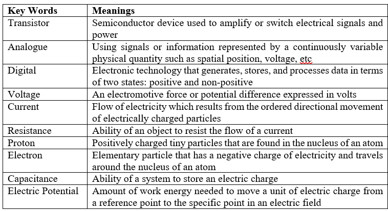
Electricity is an important topic. Electricity is like gravity. Everyone knows something about its effects, but few have any understanding of what it is. Both electricity and gravity have their origins in the fundamental structure of matter and the subatomic particles that make up matter. We use it to power our homes, watch television, play games etc. For our purposes, two of the particles that make up matter are the electron and the proton.
Introduction to Electronics
What is Electronics?
Electronics is a branch of physics and electrical engineering that deals with the emission, behaviour, and effects of electrons and with electronic devices. You get to build things that beep, whir, flash lights, and even move around the room. It encompasses an exceptionally broad range of technology.
We start with the premise that we as scientists and engineers design and built electronic systems in order to accomplish a certain task. Electronic devices help us achieve these tasks by detecting, processing and controlling various signals. Electronics exist in order to generate and process signals.
Circuit Components
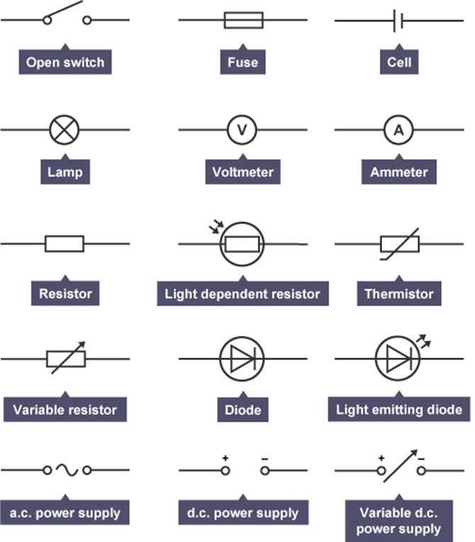
Electronics concerns itself with circuits of devices. Electrical circuits can be represented by circuit diagrams. The various electrical components are shown by using standard symbols in circuit diagrams:
· An open switch is used to turn a circuit on (closed switch) and off (open switch)
· A fuse is an electrical safety device that operates to provide overcurrent protection of an electrical circuit. Its essential component is a metal wire or strip to stop or interrupt the current. Melts and interrupts the circuit when the current becomes too strong. Once a fuse is blown, it must be replaced with a fuse of the same specification to ensure the circuit is properly protected.
· An electrical cell is an ‘electrical power supply’. A cell converts stored chemical energy into electrical potential energy, allowing positive charges to flow from the positive terminal to the negative one through an external circuit. A unit structure used to generate an electrical current by some means other than the motion of a conductor in a magnetic field. A solar cell, for example, consists of a semiconductor junction that converts sunlight directly into electricity.
· A lamp is an electrical current heats the filament in a bulb so that it gives out light. Limits the maximum current that can pass through the cell. There are two types of lamps: signal and filament
The line is a curve which suggests the resistance is changing. As the current increases the line becomes less steep and therefore the resistance becomes higher. As the current increases, the temperature of the filament wire increases. The atoms in the wire vibrate more and the electrons find it harder to flow increasing the resistance.
· Voltage is measured in units called bolts using a voltmeter which is connected in parallel in a circuit. Measures the voltage across the component. Must be placed in parallel around the component under test. It is NOT to be around the variable resistor or batter. The proper name for voltage is potential difference.
· The units for current are Amps across the component. We can put anywhere un series in the main circuit. It can NEVER be in parallel like the voltmeter. We measure current using an Ammeter which is connected in series in a circuit. Ammeters measure the cell current. The measurements of terminal pd and current for a given cell may be plotted on a graph:
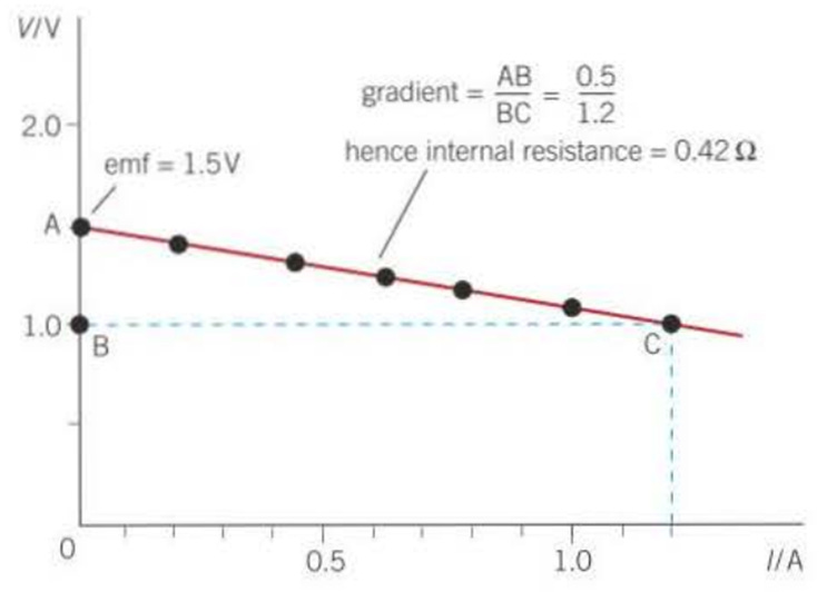
· The measurements of terminal pd and current for a given cell may be plotted on a graph. Terminal pd decreases as the current increases. This is because the lost pd increases as the current increases. The terminal pd is equal to rhe cell emf at zero current. The lost pd is zero at zero current. The graph is a straight line with a negative gradient. Seen by rearranging the equation e = 1R+ 1r to become 1R =e – 1r. 1R represents the terminal pd V, then V = e – 1r. By comparison with the standard equation for a straight line, y = m.x + c, a graph of V on the y-axis against l on the x-axis gives a straight line with a gradient-rand a y-intercept e.
· A resistor is the terminal pd is equal to rhe cell emf at zero current. The lost pd is zero at zero current. The graph is a straight line with a negative gradient. Seen by rearranging the equation e = 1R+ 1r to become 1R =e – 1r. 1R represents the terminal pd V, then V = e – 1r. By comparison with the standard equation for a straight line, y = m.x + c, a graph of V on the y-axis against l on the x-axis gives a straight line with a gradient-rand a y-intercept e.
· A light-dependent resistor (LDR) is an electronic component sensitive to light. When light falls upon it, resistance changes. Used to detect light levels, e.g in automatic security lights.
· Their resistance decreases as the light intensity increases. In the dark and at low light levels, the resistance of an LDR is high, and little current can flow through it. In bright light, the resistance of an LDR is low, and more current can flow through it. Useful for controlling how long the shutter should remain open on a digital camera. Changes in the resistance are measured and, if light level is low, shutter stays open for longer than if light level is high.
· A thermistor is an electrical resistor whose resistance is greatly reduced by heating. This is used for measurement and control. For example, a thermistor is used as temperature sensors in fire alarms. Their resistance decreases as the temperature increases. At low temperatures, the resistance of a thermistor is high and so, little current can flow through them.
· A variable resistor is a resistor whose resistance can be changed mechanically by twiddling a knob. It can be a coil of wire of a particular resistivity around a drum along which a contact moves for high currents. A variable resistor can also be a carbon track with a moving contact. We can use it as a potential divider if an extra contact is added. This is where we get a potentiometer. Good for altering the current flowing through a circuit. Resistance up means current down and vice-versa.
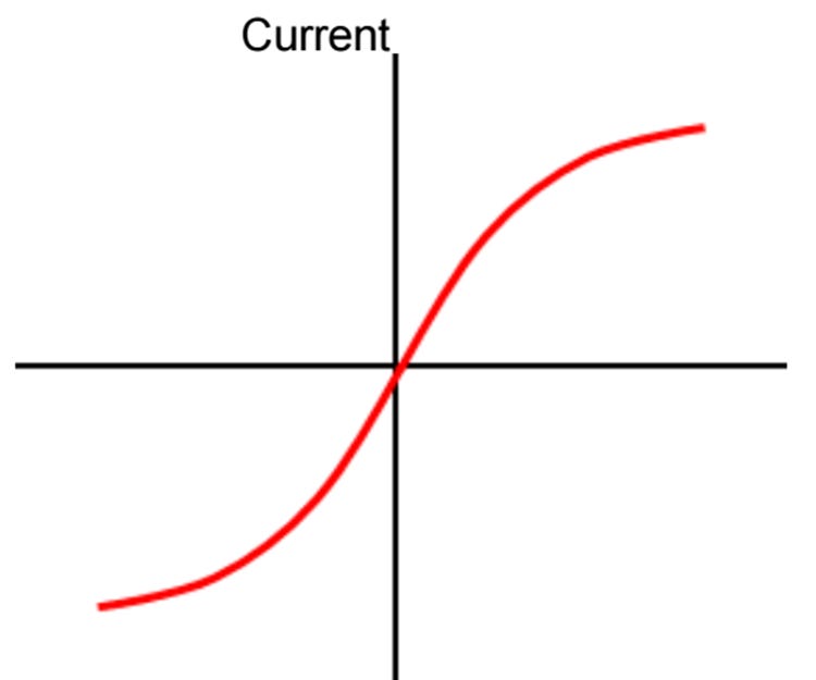
· Diodes are electronic components that can be used to regulate the voltage in circuits and to make logic gates. Light-emitting diodes (LEDs) give off light and are often used for indicator lights in electrical equipment such as computers and television sets. Very high resistance in one direction. Current can only flow in the other direction. On the top right is the graph of current against voltage for a diode. Normally a diode will not conduct until a particular voltage is reached.
· A light-emitting diode (LED) is a widely used standard source of light in electrical equipment. It has a wide range of applications ranging from your mobile phone to large advertising billboards. They mostly find applications in devices that show the time and display different types of data.
· An AC Power Supply is a type of power supply used to supply alternating current (AC) power to a load. The power input may be in an AC or DC form. The power supplied from wall outlets (mains supply) and various power storage devices is oftentimes incompatible with the power needed by the load.
· A DC Power Supply is a type of power supply that gives direct current (DC) voltage to power a device. Provides DC voltage to power a device under test such as a circuit board or electronic product. A DC power supply typically sits on an engineer's work area or bench and is often referred to as a bench power supply.
· A variable DC power supply is a type of DC power supply that allows the users to easily adjust the output voltage and current via potentiometers or a computer interface
· Adjustment is most often accomplished with a potentiometer. They can also be done with an analogue control voltage, a digital input, an autotransformer, etc.
Applications of Diodes
I introduced the subject of diodes so it is good in passing to mention some of its applications. A diode only allows current to flow in one direction:
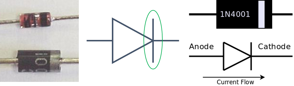
The Cathode is marked with a green band. A diode has two terminals called the Anode and Cathode. The current only flows from the Anode to the Cathode. The graph shows how the current through a diode depends on the potential difference across the diode:
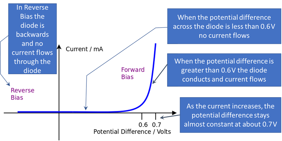
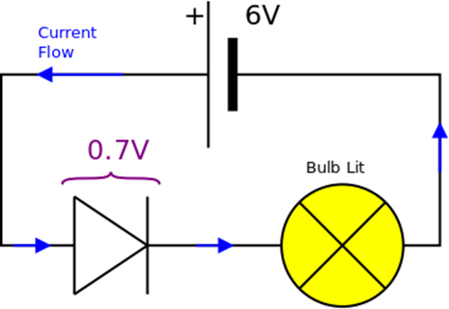
Then there is the forward bias. A forward bias is when a diode is connected so that current can flow. In the example shown below, the battery voltage is 6 V which is enough to make the diode conduct. The forward voltage drop across the diode is 0.7 V. The potential difference across the bulb is therefore 5.3 V. The diode will be damaged if too much current flows.
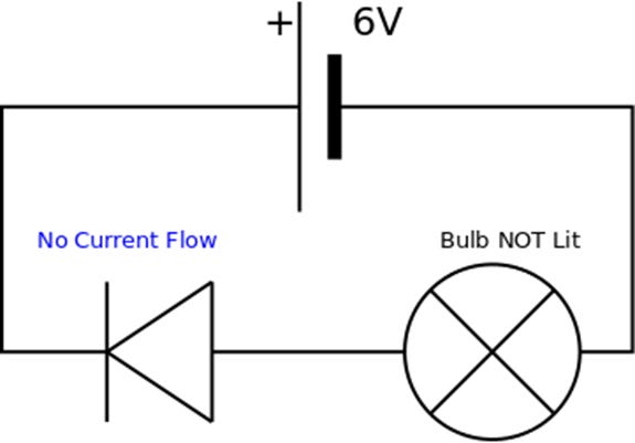
Another type of bias is the reverse bias. A reverse bias is when a diode is connected so that NO current can flow. In the example shown below, the battery voltage is 6 V but the diode is connected “backwards”. The reverse bias voltage drop across the diode is 6 V. The potential difference across the bulb is therefore zero – the bulb is not lit. The diode will be damaged if the reverse bias voltage is too great.
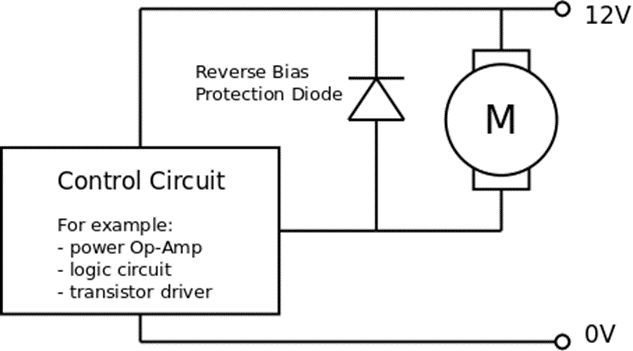
There is also a concept called the protection diode.
● Physics fact: When current suddenly stops flowing through a coil (called an inductive load) such as a motor, solenoid or relay then a large voltage is generated – this is called the “back EMF”.
● Electronics fact: The back EMF will easily damage transistors and integrated circuits that are controlling the inductive load.
● Solution: Add a diode in reverse bias across the inductive load (the motor in the diagram)
● Note: The diode protects the control circuit, not the motor
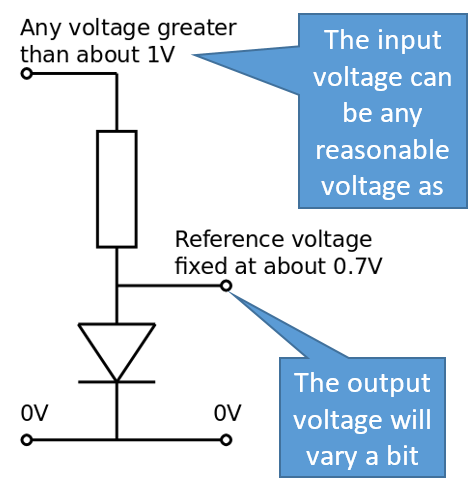
We have the voltage reference. When a reasonable current flows through a diode, the potential difference across the diode is approximately constant at about 0.7 V. A diode in a potential divider can provide a relatively constant reference voltage even when the supply voltage changes which is useful in comparator circuits.
Where does the diode fit in with the next topic: the CPU?
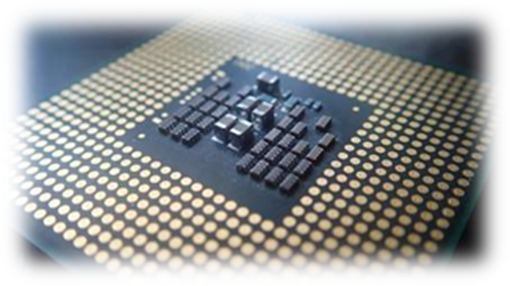
All modern Intel CPUs have a thermal diode built in amongst the millions of transistors, capacitors, and resistors that comprise the actual core of the processor. Since this diode is right there in the middle of the action, it provides the most relevant CPU temperature readings.
The Workings of the CPU
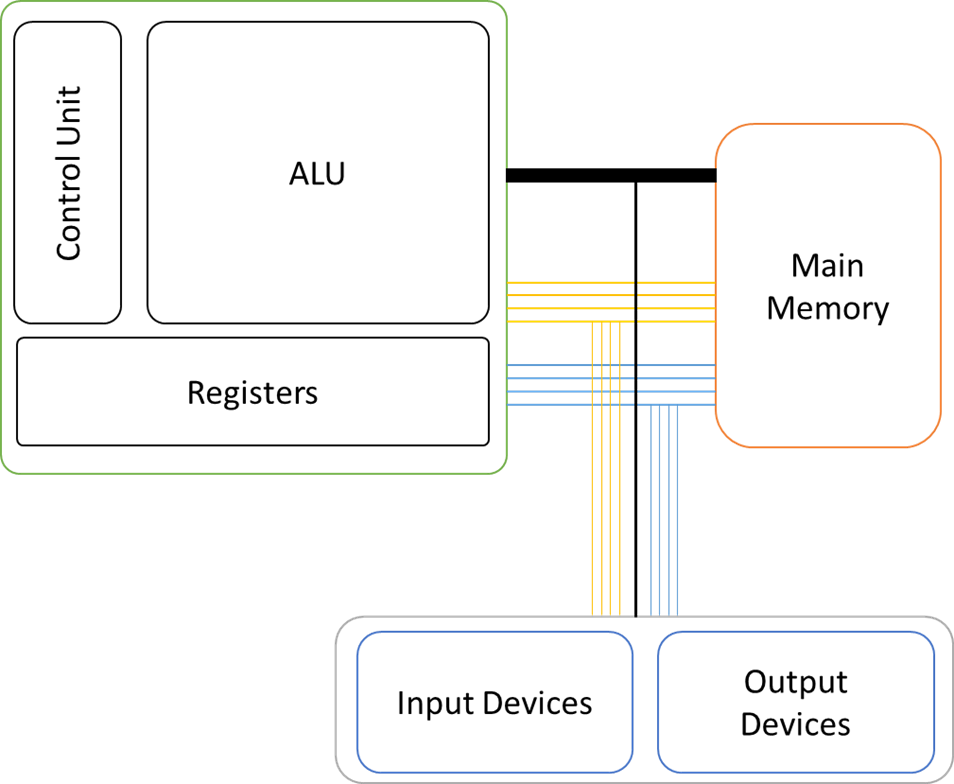
The Central Processing Unit (CPU) is the central component of a computer system. To a computer, the world consists of 0s and 1s. Inside a processor, we can store zeros and ones using transistors. Microscopic switches control the flow of electricity based on whether the switch is on or off. The transistor contains binary information: a 1 if a current passes through and a 0 if a current doesn’t pass. Transistors are located on a very thin slice of silicon. A single silicon chip can contain thousands of transistors. A single CPU contains a large number of chips. Combined, these only cover a couple of square centimetres, but can hold several million transistors and process hundreds of millions of instructions per second.
The CPU is often known as the 'brain of the computer'. Its job is to process data. And by processing we mean things like searching, sorting, calculating and decision making. Whenever you are on working on your computer, it is the CPU which is at the heart of everything. The processor is responsible for interpreting and manipulating the information contained in a computer. The CPU executes programs stored in main memory by fetching instructions and executing (running) them (Englander, 2014; Thomas, Surrall and Hamflett, 2017).
CPU Components
Control Unit
There are three main jobs of the Control Unit. It manages and monitors hardware on the computer to ensure the correct data goes to the correct hardware. It manages the input and output signals ensuring these are dealt with correctly. It manages the Fetch-Decode-Execute cycle. Altogether, they coordinate the activities taking place in the CPU, memory and peripherals This coordination is done by sending control signals to the various devices (Heathcote and Langfield, 2004; Milosevic and Williams, 2012).
Arithmetic Logic Unit
The ALU is the part of the CPU that processes and manipulates data. It performs simple calculations on the data that is temporarily stored in the registers. The ALU is also able to perform comparisons on data. It is these comparisons that allow programs to make use of choice – e.g. an IF statement in a high-level language. It has two parts:
· Arithmetic part, which performs calculations on the data, e.g. 3 + 2 = 5
· Logic part – which deals with logical operations such as is True / False / Equal to / Greater than etc.
The ALU will be able to put the answer to the arithmetic calculation into the accumulator register (Bradley, 1999). To do the specialist registers will require an article on the different computer architectures.
Cache
This part stores the data which is to be immediately processed. The CPU takes a chunk of data / instructions from the RAM and keeps it close so that it always has a constant supply of data to process. If data and instructions were downloaded from RAM one item at a time, the CPU would work far slower because the CPU cycles much faster than the RAM can deliver data. So instead, chunks are downloaded and stored on the CPU so the CPU doesn’t spend wasted time waiting for a deliver of data.
Internal Memory
Internal memory (sometimes called level 1 cache memory) is fast access temporary storage on the CPU. Data is moved from the registers to the internal memory when it is not being actively used. Data from internal memory can then either be written to RAM or called back into the registers for further processing. Cache memory size is smaller than main memory owing to its high cost. It is categorised by different levels that describe its speed, size and how close it is to the CPU:
· Level 1 cache is extremely fast but relatively small, and is usually embedded in the CPU.
· Level 2 cache often has a higher capacity than Level 1, and operates more slowly. It may be located on the CPU, dedicated to single or pairs of cores, or located on a separate chip, to avoid being slowed down by traffic on the main system bus.
· Level 3 cache works to improve the performance of Level 1 and Level 2 cache and is typically shared by all cores of a processor.
Registers
A CPU can perform each of those instructions and it does so using some very important parts of the Von Neumann Architecture. These parts are called registers, which are simply tiny memory locations (memory stores). The important ones have special names. The following registers are used during each Fetch-Decode-Execute cycle in order to carry out each instruction:
· The Accumulator (A)
· The Program Counter (C)
· The Memory Address Register (MAR)
· The Instruction Register (IR)
· The Memory Data Register (MDR)
The von Neumann Architecture needs a separate article as the way in which the registers work is quite a complex subject. There are a number of different architectures out there that would also need to be covered.
Buses
A bus is a group of wires (lines or lanes) which allows the transmission of electrical signals between components. Buses allow data to be transferred to different parts of the computer. There are three main buses used by the CPU. A processor communicates with memory and input/output (I/O) devices via the system bus. The system bus connects the most important system components such as memory and the CPU
The system bus is further sub-divided into three other buses: address bus, data bus and control bus.
Address bus
When data is saved or loaded from memory, the address at which it into be stored or loaded from must be sent. The storage address of data always travels along an address bus. Memory is divided into several fixed segments called words. The words may be of 16, 32 or 64 bits depending on the processor type. Address bus is a unidirectional bus that transmits the address from the processor to memory and input-output devices. ○In a program, the addresses of operands are sent via the address bus. The results calculated by the processor are stored in a particular memory location, the address of which is transmitted via address bus.
Data bus
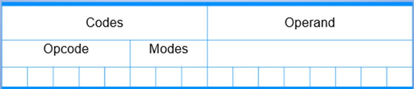
Data and instructions will then need to be moved between several parts of a computer via the data bus. Provides a bi-directional path to do this. The width of the data bus is a key factor in determining overall system performance. For example, if the data bus is 8-bits wide and each instruction is 16-bits long, the CPU must access the main memory twice to fetch an instruction. This bus is used to transmit data and instructions between the processor, memory and input-output devices. Let us consider a data bus that is 8 bits wide. It will be able to hold values ranging from 0 to 28-1 (255). With a data bus that is 16 bits wide, the values up to of 216-1 (65535) shall be transmitted. Consider a microprocessor with a 16-bit data bus. For example, it is separated as 5-bit for opcodes, 3-bits for modes and 8-bits for operands. 25=32 different instructions may be programmed into this processor.
Control bus
The controller uses the control bus to send control signals to different parts of the computer. Controls lines must be provided to ensure access to and use of the data and address buses by different components doesn’t lead to conflict. Transmits command, timing and specific status information between components and what operations to perform. The different control signals are: Clock; Memory Read; and Memory Write
· Clock: Synchronises the operations on a computer.
· Memory Read: The contents in the specified address is copied to the data bus.
· Memory Write: The contents in the data bus is copied to the specified address.
· The different control signals are: Bus Request; Bus Grant; and Interrupt Request
· Bus Request: A device requests to use the data bus so that it can perform the Read/Write operation
· Bus Grant: The signal from the CPU indicating that the device is granted access to use the data bus
· Interrupt Request: A signal sent from a device or software to the processor which temporarily stops the current process and initiates an interrupt service routine. An interrupt request is a signal sent by the device requesting access to the processor.
CPU Characteristics
CPU characteristics are broken down into the following areas:
· Processor/Clock Speed
· Cache Size
· Overclocking - that will be viewed in another section in more detail
Processor/Clock Speed
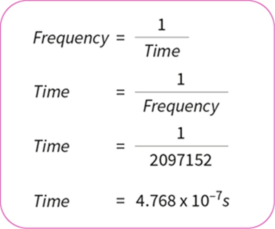
The clock speed is the speed at which a processor operates. The faster the clock speed, the faster the computer is able to run the fetch-decode-execute cycle and therefore process more instructions. The speed of the Fetch-Decode-Execute cycle is determined by the CPU’s clock chip. This chip uses a vibrating crystal that maintains a constant rate. The speed of the clock is measured in hertz (Hz) which is the amount of cycles per second.

A clock speed of 500Hz means 500 cycles per second. Current computers have CPU clock speeds of 3GHz which means 3 Billion cycles per second. During a clock cycle the processor can fetch, decode and execute a simple instruction, such as load, store or jump. More complex instructions take more than one clock cycle. It is easy to calculate the amount of time it takes to run one cycle for any speed of processor. The calculation for a 2 gigahertz (GHz) processor:
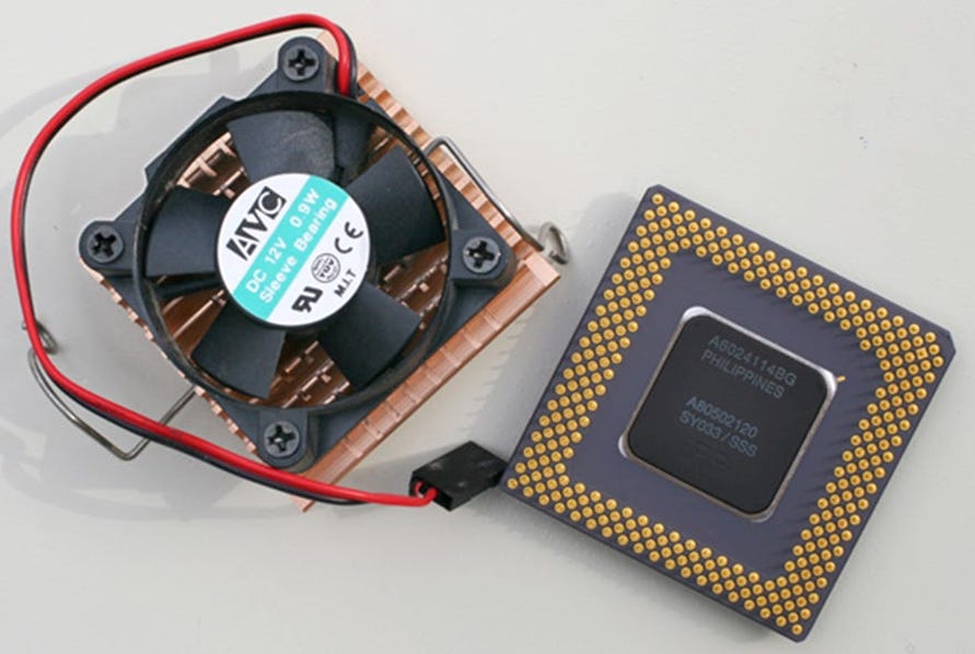
Processors are getting to the point where it is hard to increase speed. When the number of clock cycles per second is increased, the transistors within the processor have to switch faster, which generates more heat. Unless the heat is drawn away from the processor, it can easily overheat. A processor can reach temperatures in excess of 300 degrees Celsius, which is hotter than an oven, in a matter of seconds. If you open up a desktop PC, you will see a large heat sink and fan attached to the processor, which has the job of pulling all of this heat away from the processor. You should never run a system without a heat sink as this could cause permanent damage to both the processor and the motherboard. It could also pose a severe fire risk.
Processor manufacturers, such as AMD or Intel, try other methods to increase the performance of their CPUs. This can include increasing the number of cores (processors) in the CPU, making existing circuitry more efficient, or developing new instructions. In order to make a fair comparison of these processors, they should be subjected to controlled tests.
Cache
Cache is a high-speed access area that can be a reserved section of main memory or on a storage device. Stores recently used information so that it can be quickly accessed at a later time. Computers incorporate several different types of caching in order to run more efficiently, thereby improving performance. Common types of caches include browser cache, disk cache, memory cache, and processor cache.
Physics of Overclocking the CPU
Overclocking is a way of configuring a computer to perform faster than its advertised speed. It uses more energy and produces more heat. If this heat isn’t removed through cooling, the CPU can overheat. It will damage the CPU and shorten its lifespan. Where’s the physics?
Yes, there is physics in relation to the overclocking the CPU. There is some element of physics when it comes to overclocking the CPU. If there isn’t enough electrical current to power the processor at the new rate, it may slow down or stop running completely. When we overclock CPU or GPU or RAM we also have to increase the voltage to achieve stable operation provided we have adequate cooling. As a chip’s clock rate and voltage are increased, the waste heat output of the system also increases quickly (Fabron, 2016).
The potential to cause damage and voiding of warranties are two often-cited reasons that people are hesitant about overclocking. Damaging components due to heat or voltage overloads was easy in the old days, and it is still possible now. Today, manufacturers incorporate a number of fail-safes, including thermal throttling. It is far more likely that a system will become unstable and crash before there is any permanent damage caused by a short-term test run. Thermal throttling is one method used to protect your GPU from damage (Fabron, 2016). In many cases, thermal throttling occurs when a PC's ambient temperature gets too hot. This is good for the CPU as it can cool itself down to a point where it won’t overheat. Overclocking reduces the lifespan of system components. In electronics, the biggest source of wear is a phenomenon known as electromigration. Ions are slowly transferred from a structure to the adjacent structure under the force of electrical current. Major contributing factors include increased heat and voltage, but the limits of heat and voltage vary with different materials, different production technologies, and expected component lifespan. Thermal loads in particular tend to accelerate electromigration in integrated circuits (ICs). Some designers are however, finding ways to reduce CPU core voltage while maintaining processor performance. The aim is to reduce the chances of overheating. Another concern with a high CPU core voltage is wear and tear on the processor. Higher voltages tend to result in shortened CPU lives, especially if machines are required to be powered on for extended periods of time (Akers, 2023).
During switching, it takes time for the signals to reach their final voltage. If you tell them to switch more often, they eventually don't reach their needed 'threshold voltage' before they are told to switch back again. The threshold voltage is an internal design parameter in the chips and is the 'decision point' where the chip decides if the signal is High or Low. It is relatively stable over supply voltage. Just like a DC motor, the higher the applied voltage, the faster the signals will change level; and the sooner the chips detect the level change. That's the 'easy' version, the full version needs a lengthy study in physics, electronic design, and solid state physics (Fabron, 2016).
The physics around overclocking the CPU can be broken down into a few aspects:
· Threshold Voltage
· Applied Voltage
· Near-Threshold Voltage
· Electronic Design
· Solid-State Physics
· Subthreshold leakage
· Voltage Regulator Module
These bullet points are NOT limited – there is more that goes beyond the scope our objective.
Threshold Voltage
The threshold voltage is the voltage at which a transistor begins to conduct electricity. A current starts to be generated when the threshold voltage is at around 0.2-0.3V in modern process technology. Modern chips are largely composed of digital logic and memory, along with portions of analogue and I/O circuitry. At a high level, CPUs and GPUs resemble large islands of memory for caches and cores. Even logic such as a floating point unit contains memory elements though, such as register files and latches to hold intermediate data values. Logic is largely dominated by combinatorial logic and wiring, rather than data storage elements.
Applied Voltage
Applied voltage to a component is the actual voltage given to the component. We are creating a difference in electric potential energy between two points. Area of concern in this context is leakage power. Silicon transistors can leak current across junctions and to the substrate. The amount of leakage current in a processor of a particular process type varies largely by applied voltage and temperature. The applied voltage can become quite significant in today's high-performance processors. These are the same factors that are required to make transistors switch faster also increase leakage. All this leakage current creates additional power that must be counted as part of the device’s total power consumption. As a result, there is a reduction in the amount of the device’s total power envelope that can be consumed as active power.
Near-Threshold Voltage
Near-Threshold Voltage means computing at a point of peak energy efficiency. The circuit starts to transition from a 1 to a 0 or 0 to a 1. With an option to lower power consumption, it can’t reduce the power of the wireless transceiver and receiver. For most Intel CPUs that came out within the last five years, you will want to stay at or below 1.3 volts if you want to be relatively safe. 1.5 volts is almost always dangerous for modern CPUs (Fabron, 2016).
Electronic Design
Electronic Design is the involvement of software tools for the creation and development of integrated circuits and systems. Electronic design software and tools work together in a design flow that designers use to design and analyse semiconductor circuits. In the context of the CPU, electronic design focuses on creating the CPU itself.
In relation to electronic design, the design process when it comes to the CPU involves choosing an instruction set and a certain execution paradigm such as RISC, CISC or VLIW and also results in a microarchitecture that may be describes in VHDL. VDHL is the most important of the hardware description languages, which can be used for many purposes including documentation, synthesis, simulation, verification and testing of circuits. We can use VDHL to describe the structure, data flow or system behaviour and can be used in numerous ways within the developmental process (Storey, 2009).
For microprocessor design, this description is then manufactured employing some of the various semiconductor device fabrication processes. These result in a die, which is bonded onto a chip carrier. This chip carrier is then soldered onto, or inserted into a socket on a printed circuit board (PCB). In the case of the CPU, this will be the motherboard as it holds the principal components of a computer system. This is the most important component of a computer system. The motherboard contains at least the main bus. The CPU will likely be soldered to the motherboard but, it can also be plugged into the motherboard (British Computer Society. Glossary Working Party, 2005; Anderson et al., 2012).
Solid-State Physics
Solid State Physics by definition means studying rigid matter or solids, through methods like quantum mechanics, crystallography, electromagnetism, and metallurgy. Solid state physics allows to understand the limitations in the miniaturisation of transistors. It is required to understand the influence of the defects on the physical mechanisms. Without a strong research in solid state physics it would have been impossible to reach today performances.
Subthreshold leakage
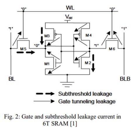
The subthreshold leakage is the drain source current of a transistor when the gate source voltage (Vgs) is less than the threshold voltage. The subthreshold current depends on threshold voltage exponentially, which results in large subthreshold current especially short channel devices. The subthreshold current depends on the threshold voltage exponentially. This will result in large subthreshold current. This is especially the case with short channel devices. In fig. 2 below, the subthreshold leakage current is shown by the dotted arrow:
In relation to the subthreshold leakage, the operating temperature can have a significant impact on the behaviour of microprocessors and other semiconductors in terms of performance, power consumption and reliability. Cooler chips actually run faster. Both transistors and metal interconnects slow down at higher temperatures. As transistors heat up, resistance goes up, which lowers the current when the transistor is on. The resistance of almost exclusively copper wiring also gets worse with temperature, as the copper atoms become more energetic and have a higher chance of colliding with electrons. Studies have shown that basic circuits (e.g. NAND, NOR, adder) slow down by 5-11% as the temperature rises from 0C to 125C, and the impact is up to 14% for circuits using dynamic logic. A more effective and realistic cooling solution will not reduce the temperature of a chip to 0C, but it’s quite possible to keep things under 40C, and this could easily yield 4-8% faster circuits. The impact of temperature on frequency is fairly modest, but the influence on leakage power is tremendous (Kanter, 2011).
Voltage Regulator Module
VRM stands for voltage regulator module. A VRM is a specialised point-of-load (PoL) power converter. Some modern CPUs and GPUs use VRMs to control and lower the voltage sent to these components in order to avoid exceeding their maximum voltage capabilities. VRMs are especially important for overclocking a CPU or GPU. In theory, VRMs should mean the power supplied to the component is consistent and steady. VRMs are buck connectors. This means they are DC-to-DC power converters (Harding, 2018; Shephard, 2018).
Conclusion
From what you have read in this article, the physics of the CPU is so vast it would need at least another two long articles to cover everything. In short, this is only a snapshot of the physics of the CPU, including overclocking the CPU. Hopefully, this article will have given you an idea in relation to the knowledge of the CPU regarding its workings and the physics and electronics behind it.
Reference List
Akers, H. (2023) ‘What Is CPU Core Voltage?’ Easy Tech Junkie 25th May Available at: https://www.easytechjunkie.com/what-is-cpu-core-voltage.htm (Date Accessed: 11/06/2023)
Anderson, L Jarvis, A. Kaye, A. Lawson, J. McGill. R. Phillips, J. Smith, A. (2010) Information Technology Level 3 Book 1 Harlow, Essex: Pearson Education Limited
Arctic Silver (2007) ‘Calibrating The Internal Thermal Diode In An Intel PIII CPU’ Available at: https://www.arcticsilver.com/PDF/WhtPr/CalibratingPIII_InternalThermoDiode.pdf (Date Accessed: 08/06/2023)
Bradley, R. (1999) Understanding Computer Science to Advanced Level Fourth Edition Cheltenham: Stanley Thornes (Publishers) Limited
British Computer Society. Glossary Working Party, (2005) The BCS Glossary of ICT and Computing Terms Eleventh Edition Harlow, Essex: Pearson Education Limited
Englander, I. (2014) The Architecture of Computer Hardware, Systems Software and Networking An Information Technology Approach Fifth Edition, Hokoben, New Jersey: John Wiley and Sons Inc
Fabron, G. (2016) ‘CPU Overclocking Guide: How (and Why) to Tweak Your Processor’ Tom’s Hardware 14th July Available at: https://www.tomshardware.com/reviews/cpu-overclocking-guide,4593.html (Date Accessed: 11/06/2023)
Harding, S. (2018) ‘What Is a VRM? A Basic Definition’ Tom’s Hardware 12th December Available at: https://www.tomshardware.com/reviews/vrm-voltage-regulator-module-definition,5771.html (Date Accessed: 08/06/2023)
Heathcote, P.M. Langfield, S. (2004) A Level Computing 5th Edition. Oxford: Payne-Gallway Publishers Ltd
Kanter, D. (2011) ‘What Do Overclockers and Supercomputers Have in Common?’ 20th June Real World Tech Available at: https://www.realworldtech.com/supercomputers-cooling/2/ (Date Accessed: 08/06/2023)
Milosevic, A. Williams, D. (2012) F451 - Computing Fundamentals Revision Guide, Headington, Oxford: Bagatelle Publications Ltd
Milosevic, A. Williams, D. (2012) F453 – Advanced Computing Theory Revision Guide. Headington, Oxford: Bagatelle Publications Ltd
McComb, G. Boysen, E. (2005) Electronics for dummies, Hoboken, New Jersey: John Wiley & Sons.
Shephard, J. (2018) ‘What’s a voltage regulator module?’ Power Electronic Tips 7th July Available at: https://www.powerelectronictips.com/whats-a-voltage-regulator-module-faq/ (Date Accessed: 08/06/2023)
Storey, N. (2009) Electronics A Systems Approach Fourth Edition, Harlow, Essex: Pearson Education Limited
SVIT, V. CSITC, C. (2013) ‘Leakage current reduction techniques in SRAM’, International Journal of Engineering Research & Technology (IJERT) Vol. 2 (Issue 1) pp. 1-5
Thomas, M. Surrall, A. Hamflett, A. (2017) A/AS Level Computer Science for WJEC/Eduqas Student Book Cambridge: Cambridge University Press
To keep updated on my work, please click the subscribe button: